
Intro
The land of tomorrow is slowly becoming the land of today. Robots might one day take over the world, but for now we still start by remotely controlling them with an internet connection. In this article we will create an HTML page that allows the user to control their robot’s movements using MQTT to send commands, while also remotely viewing the surroundings with a webcam mounted on the robot.
This remote control will lay a foundation that can be used as a stepping stone when adding features in the future.
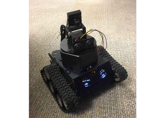
Figure 1: The DFRobot Devastator Robot fully assembled
For the purposes of this article, we used the DFRobot* Devastator Robot.
You can find it here:
https://www.dfrobot.com/index.php?route=product/product&search=edison&description=true&product_id=1379.
It is a tank style robot with two motors that also comes with a number of sensors and a camera. However, this article and code can be easily used with other comparable microcontroller robots, and even adapted for other projects.
If you want to learn more about the DFRobot Devastator Robot, see my colleagues article here:https://software.intel.com/en-us/articles/overview-of-intel-edison-based-robotics-platform
Note: The Devastator’s battery pack is only 9V with 6 AA batteries, which is not sufficient once all the motors and the camera are mounted for this project. An additional 2 AA battery pack must be connected in series to the 9V one to give the robot 12V needed for the purposes of this article.
Setting up the Camera
The Devastator Robot kit comes with a USB camera and a pan tilt kit which need to be assembled and attached to the base. If creating your own DIY robot using the Intel® Edison module and a USB camera, note that the camera must be UVC compliant to ensure that it is compatible with the module’s USB drivers. For a list of UVC compliant devices see this webpage here:
http://www.ideasonboard.org/uvc/#devices.
On the Devastator Robot, plug the USB webcam into the micro OTG USB port using the OTG USB adapter and plug another cable into the other micro USB port from your computer.
To ensure the USB webcam is working, type the following into a serial connection. (Using PuTTY)
ls -l /dev/video0
A line similar to this one should appear:
crw-rw—- 1 root video 81, 0 May 6 22:36 /dev/video0
Otherwise, this line will appear indicated the camera is not found.
ls: cannot access /dev/video0: No such file or directory
Next, install the mjpeg-streamer library on the Intel® Edison module.
Do this by adding the following lines to base-feeds.conf:
echo "src/gz all http://repo.opkg.net/edison/repo/all
src/gz edison http://repo.opkg.net/edison/repo/edison
src/gz core2-32 http://repo.opkg.net/edison/repo/core2-32" >> /etc/opkg/base-
Update the repository index:
opkg update
To the start the stream:
mjpg_streamer -i "input_uvc.so -n -f 10 -r 400×400" -o "output_http.so -p 8080 -w ./www"
Note that the frame rate (-f 10) and size (400×400) has been limited to reduce power and computational demands and help ensure an up-to-date image without the stream freezing.
To view the stream while on the same Wi-Fi* network, replace ‘localhost’ in the following URL with the IP address of the Intel® Edison module: http://localhost:8080/?action=stream
A still image of the feed can also be viewed by replacing ‘localhost’ in the following URL with the IP address of the Intel® Edison module: http://localhost:8080/?action=snapshot.
To make the camera feed visible from outside the Wi-Fi network, you will need to configure your router properly. Detailed instructions can be found here:https://ipcamnetwork.wordpress.com/2010/09/23/acessing-your-camera-from-the-internet/
We also need to have the camera start-up at boot time, so it is ready for use. First create a script in the/home/root/ directory.
1vi cameraScript.sh
Add the following to the script.
#!/bin/sh
mjpg_streamer -i "input_uvc.so -n -f 10 -r 400×400" -o "output_http.so -p 8080 -w ./www"
Make the script executable.
chmod +x /home/root/ cameraScript.sh
chmod +x cameraScript.sh
And make it start up on boot:
update-rc.d cameraScript.sh defaults
To make sure it works, reboot the Intel® Edison module. (This step assumes it is also configured to connect to Wi-Fi).
reboot
HTML WebPage
To remotely control the robot, a simple HTML webpage is created as it easily ties into the webcam stream and is compatible across a broad number of platforms. On your computer you will have an index.html file and a script.js file in the same location. Double clicking on the index.html file will start up the webpage.
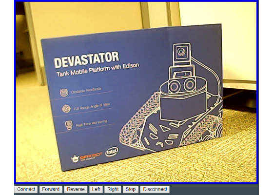
Figure 2: Screenshot of the HTML page with webcam view and control buttons
The index.html file code is below. As the robot is using MQTT and we need some custom methods, we include the mqttws31.js and our own script.js. We also need an object to contain the web stream and some buttons to control the robot.
<!DOCTYPE html>
<html>
<head>
<title>NodeJS Starter Application</title>
<meta charset="utf-8">
<meta http-equiv="X-UA-Compatible" content="IE=edge">
<meta name="viewport" content="width=device-width, initial-scale=1">
<link rel="stylesheet" href="stylesheets/style.css">
<script src="https://cdnjs.cloudflare.com/ajax/libs/paho-mqtt/1.0.1/mqttws31.js" type="text/javascript"></script>
<script src="script.js"></script>
</head>
<body>
<div>
<object type="text/html" data="http://192.168.1.104:8080/?action=stream" width="640px" height="480px" style="overflow:auto;border:5px ridge blue">
</object>
</div>
<div>
<input onclick="client.connect(options);" type="button" value="Connect" id="connect"></input>
<input onclick="publish('forward','dfrobotControl',2);moveForward();" type="button" value="Forward" id="forwardButton"></input>
<input onclick="publish('reverse','dfrobotControl',2);moveReverse();" type="button" value="Reverse" id="reverseButton"></input>
<input onclick="publish('left','dfrobotControl',2);moveLeft();" type="button" value="Left" id="leftButton"></input>
<input onclick="publish('right','dfrobotControl',2);moveRight();" type="button" value="Right" id="rightButton"></input>
<input onclick="publish('stop','dfrobotControl',2);moveStop();" type="button" value="Stop" id="stopButton"></input>
<input onclick="client.disconnect();" type="button" value="Disconnect" id="disconnect"></input>
<div id="messages"></div>
</div>
</body>
</html>
Code Sample 1: index.html file
The script.js will highlight the current command button and also handle the MQTT connect and subscribe logic.
Take note of the client instance line in the script.js:
var client = new Paho.MQTT.Client("broker.hivemq.com", 8000, "clientId");
We are using broker.hivemq.com as our MQTT server. It is free to use and allows you to setup your own broker using their services if needed. The clientId must be unique for each client so be sure to change it to something else, maybe even add some random characters and numbers in as well. Also the topic that the robot is using for subscribing and publishing is dfrobotControl, but you can change it to suit your own purposes.
function moveForward()
{
clearButtons();
document.getElementById("forwardButton").style.color = "red";
};
function moveReverse()
{
clearButtons();
document.getElementById("reverseButton").style.color = "red";
};
function moveLeft()
{
clearButtons();
document.getElementById("leftButton").style.color = "red";
};
function moveRight()
{
clearButtons();
document.getElementById("rightButton").style.color = "red";
};
function moveStop()
{
clearButtons();
document.getElementById("stopButton").style.color = "red";
};
function clearButtons()
{
document.getElementById("forwardButton").style.color = "black";
document.getElementById("reverseButton").style.color = "black";
document.getElementById("leftButton").style.color = "black";
document.getElementById("rightButton").style.color = "black";
document.getElementById("stopButton").style.color = "black";
};
// Create a client instance
var client = new Paho.MQTT.Client("broker.hivemq.com", 8000, "clientId");
// called when the client loses its connection
client.onConnectionLost = function (responseObject) {
alert("connection lost: " + responseObject.errorMessage);
};
//Connect Options
var options = {
timeout: 3,
//Gets Called if the connection has sucessfully been established
onSuccess: function () {
alert("Connected");
//and subscribe to the topic
client.subscribe('dfrobotControl/#', {qos: 2});
alert('Subscribed');
},
//Gets Called if the connection could not be established
onFailure: function (message) {
alert("Connection failed: " + message.errorMessage);
}
};
//Publish the message to the topic
var publish = function (payload, topic, qos) {
var message = new Paho.MQTT.Message(payload);
message.destinationName = topic;
message.qos = qos;
client.send(message);
}
Code Sample 2: script.js file for the HTML page
Arduino Sketch
The Devastator uses the Romeo board for Intel® Edison module which by default is programmable with the Arduino* IDE. In the Arduino sketch we need to subscribe to the MQTT topic to receive the commands and then act on them. The webcam is already taken care of, but we will set a static IP address for the Intel® Edison module as well as connect it to Wi-Fi* network. Once set up in this way, the webcam IP will always be the same for the webpage.
The front LEDs are used as a status indicators. When the Wi-Fi connection is successful, the robot’s right LED will illuminate. When MQTT successfully connects and subscribes, the robot’s left LED will illuminate.
#include <SPI.h>
#include <WiFi.h>
#include <PubSubClient.h>
#include <DFRobot.h>
#include <IIC1.h>
// WiFi Login
IPAddress ip(192, 168, 1, 104);
char ssid[] = "wifiname"; // your network SSID (name)
char pass[] = "wifipassword"; // your network password
const char* server = "broker.mqttdashboard.com";
// WiFi connection
WiFiClient wifiClient;
int status = WL_IDLE_STATUS; // the Wifi radio's status
#define leftLEDPin 7
#define rightLEDPin 10
DFrobotEdison MotorLeft;
DFrobotEdison MotorRight;
The next step in the code is the callback method for when a message is published to the MQTT topic. The sketch is actively listening for a message to arrive and once it does, the appropriate command can be called.
void callback(char* topic, byte* payload, unsigned int length) {
Serial.print("Message arrived [");
Serial.print(topic);
Serial.print("] ");
String message= "";
for (int i=0;i<length;i++) {
Serial.print((char)payload[i]);
message= message + (char)payload[i];
}
Serial.println();
String forward= "forward";
if (message.equals("forward") == 1) {
Serial.println("Forward!!!");
motorForward();
}
if (message.equals("reverse") == 1) {
motorBackward();
Serial.println("reverse!!!");
}
if (message.equals("left") == 1) {
motorLeft();
Serial.println("left!!!");
}
if (message.equals("right") == 1) {
motorRight();
Serial.println("right!!!");
}
if (message.equals("stop") == 1) {
motorStop();
}
}
// PubSub Client.
PubSubClient client(server, 1883, callback , wifiClient);
When connecting to the MQTT server, remember to choose a unique clientID for the Intel® Edison module to use and change the topic as well if necessary. Accomplish this by updating the client.connect("clientID ")) and client.subscribe("dfrobotControl") lines.
void reconnectMQTT() {
// Loop until we're reconnected
digitalWrite(leftLEDPin, LOW);
motorStop();
while (!client.connected()) {
Serial.print("Attempting MQTT connection…");
// Attempt to connect
if (client.connect("clientID ")) {
Serial.println("connected");
// … and resubscribe
client.subscribe("dfrobotControl");
digitalWrite(leftLEDPin, HIGH);
} else {
Serial.print("failed, rc=");
Serial.print(client.state());
Serial.println(" try again in 5 seconds");
// Wait 5 seconds before retrying
delay(5000);
}
}
}
void reconnectWiFi() {
// Loop until we're reconnected
digitalWrite(rightLEDPin, LOW);
digitalWrite(leftLEDPin, LOW);
motorStop();
status = WiFi.begin(ssid, pass);
while(!(status == WL_CONNECTED)){
Serial.println("WiFi Failed!");
status = WiFi.begin(ssid, pass);
delay(5000);
}
Serial.println("WiFi Connected!");
digitalWrite(rightLEDPin, HIGH);
}
void setup()
{
Serial.begin(9600);
Serial.println("Init the sensor");
//Initilize Pin Mode
pinMode(rightLEDPin, OUTPUT);
pinMode(leftLEDPin,OUTPUT);
digitalWrite(rightLEDPin, LOW);
digitalWrite(leftLEDPin, LOW);
//Initilize Motor Drivers
MotorLeft.begin(M2);
MotorRight.begin(M1);
WiFi.config(ip);
status = WiFi.begin(ssid, pass);
while(!(status == WL_CONNECTED)){
Serial.println("WiFi Failed!");
status = WiFi.begin(ssid, pass);
delay(5000);
}
Serial.println("WiFi Connected!");
digitalWrite(rightLEDPin, HIGH);
}
void loop()
{
client.loop();
if (!client.connected()) {
reconnectMQTT();
}
if(WiFi.status()!= WL_CONNECTED){
reconnectWiFi();
}
delay(1000);
}
And finally the methods to control the robot’s movement.
void motorBackward()
{
motorStop();
MotorLeft.setDirection(ANTICLOCKWISE);
MotorRight.setDirection(ANTICLOCKWISE);
for(int i=0;i<150;i+=10)
{
MotorLeft.setSpeed(i);
MotorRight.setSpeed(i);
delay(20);
}
}
void motorForward()
{
motorStop();
MotorLeft.setDirection(CLOCKWISE);
MotorRight.setDirection(CLOCKWISE);
for(int i=0;i<150;i+=10)
{
MotorLeft.setSpeed(i);
MotorRight.setSpeed(i);
delay(20);
}
}
inline void motorLeft()
{
motorStop();
MotorLeft.setDirection(ANTICLOCKWISE);
MotorRight.setDirection(CLOCKWISE);
for(int i=0;i<150;i+=10)
{
MotorLeft.setSpeed(i);
MotorRight.setSpeed(i);
delay(20);
}
}
inline void motorRight()
{
motorStop();
MotorLeft.setDirection(CLOCKWISE);
MotorRight.setDirection(ANTICLOCKWISE);
for(int i=0;i<150;i+=10)
{
MotorLeft.setSpeed(i);
MotorRight.setSpeed(i);
delay(20);
}
}
inline void motorStop()
{
MotorLeft.setSpeed(0);
MotorRight.setSpeed(0);
delay(50);
}
Code Sample 3: Arduino sketch to control the robot
For more such intel IoT resources and tools from Intel, please visit the Intel® Developer Zone
Source:https://software.intel.com/en-us/articles/using-the-intel-edison-module-to-control-robots


